
Contents
The following shall explain the ARC1 firmware architecture and the DCC signal generation in detail.
Main Program
 |
|
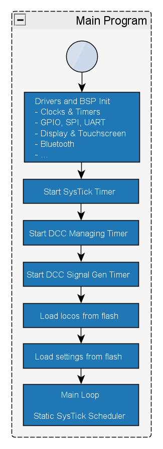
After system power-on, the firmware will initialize the device drivers (e.g. for serial communication, digital I/O, flash, timers etc.) and the Board Support Package (BSP) for components such as display, touchscreen, SDRAM, LED ring etc. As the firmware is mainly based on static scheduling and timer interrupts, these timers have to be configured and started next. After loading the global user settings and saved locomotives from non-volatile flash memory, the firmware starts operation with a static scheduler controlling the execution of different tasks. The 100Hz-task for capturing user inputs and managing the graphical user interface (GUI) is the most important one.
SysTick Timer 100Hz-Task
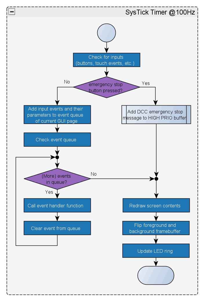 |
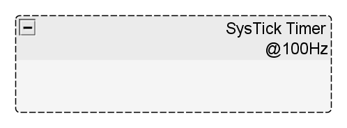
With 100Hz (every 10ms), the firmware checks the touchscreen, buttons and speed knob for new inputs and creates events for the current GUI page in a dynamic event buffer respectively. The use of a dynamic event buffer enables ARC1 to capture and process parallel events, as for example the simultaneous operation of speed knob and buttons. Only the emergency stop button will directly trigger a DCC emergency stop message on the rails without generating an event first. After capturing the user inputs, the event buffer will get processed and the corresponding event-callback functions will be triggered. Within the callback functions, the interaction and display update will take place.
DCC Managing Timer IRQ
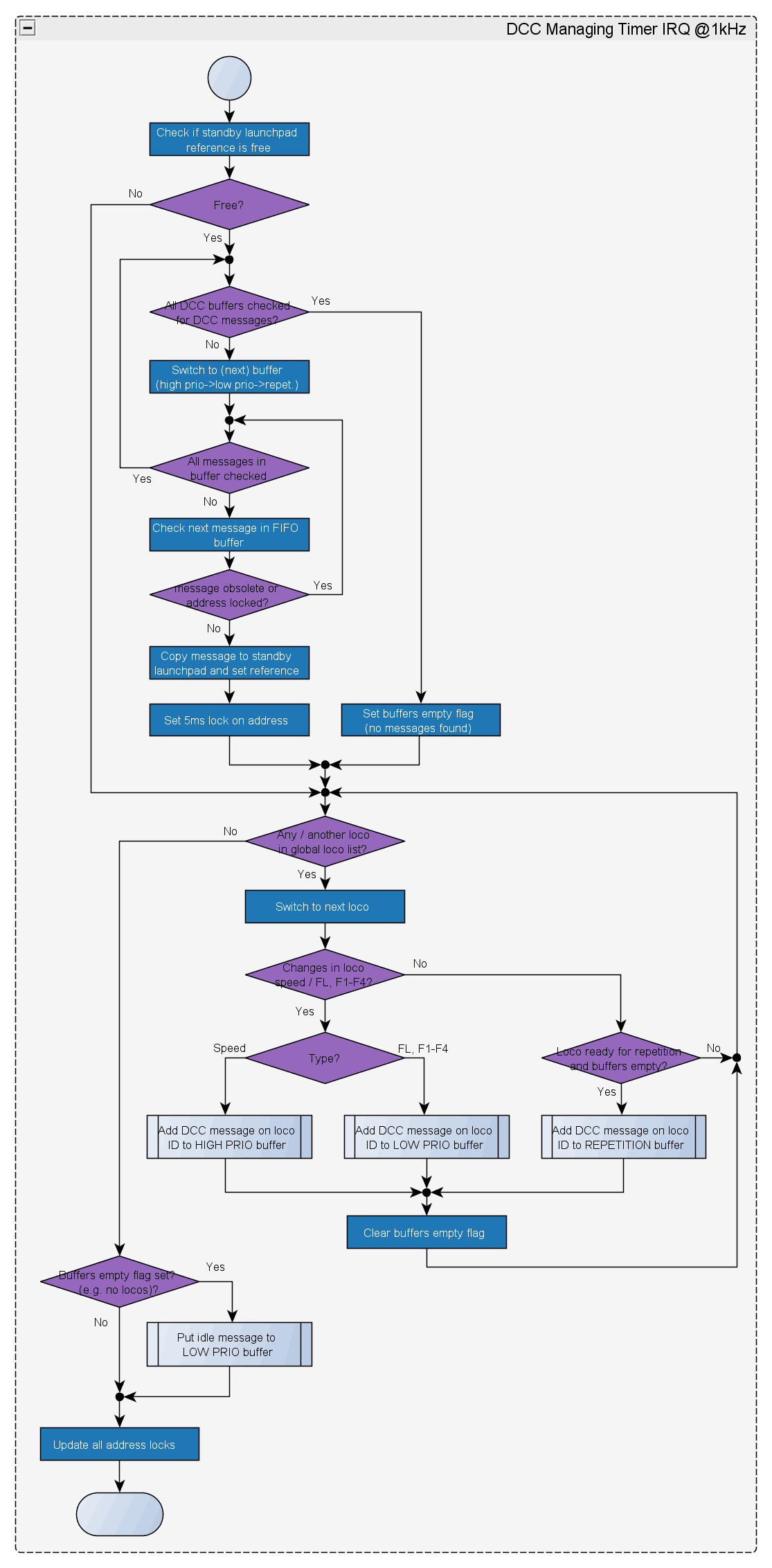 |
The DCC Manager is optimized for maximum DCC bandwidth utilization and the parallel operation of multiple locomotives. Three priority-based DCC signal buffers are used to manage and handle the generation of DCC commands. To separate the management of these buffers from the real-time generation of logical signals, the addresses of two protected memory areas – the so-called “launchpads” – are alternately passed to the DCC signal generator. In this way, a new message can already be copied from one of the buffers to the standby launchpad, while the active launchpad still gets processed by the signal generator.
The three priority-based DCC signal buffers are FIFO ring-buffers: a high-prio buffer for speed-commands, a low-prio buffer e.g. for light and function commands and a repetition-buffer. The repetition-buffer has the lowest priority and is used to instantaneously repeat high- and low-prio messages and to re-transmit all locomotive states on the rails periodically. This is necessary in order to keep a locomotive operating after a decoder reset due to poor rail connection.
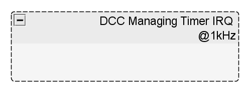
The DCC Manager is interrupt controlled and works with 1kHz. After the interrupt was thrown, the three buffers are processed in order of their priority while searching for DCC commands that are not yet gone obsolete by a newer command to the same locomotive and whose locomotive address is not locked with a 5ms address-lock (compare NMRA S-9.2, Frequency Of Packet Transmission). If a valid command is found and if the standby launchpad is not yet assigned, the respective message will be copied to the launchpad and its address will be locked for 5ms. If no valid message was found in any of the buffers, a flag for command repetition is set. After processing the buffers, all locomotives are checked for changes in their states (e.g. speed, light, functions) and command messages are added to the buffers accordingly. In case there are no changes and the flag for command repetition was set before (all buffers were empty), the states of all locomotives are re-transmitted consecutively. If no locomotives are saved on ARC1, idle messages are generated in order to avoid that locomotives on the rails will switch to analog operations mode.
DCC Signal Generation
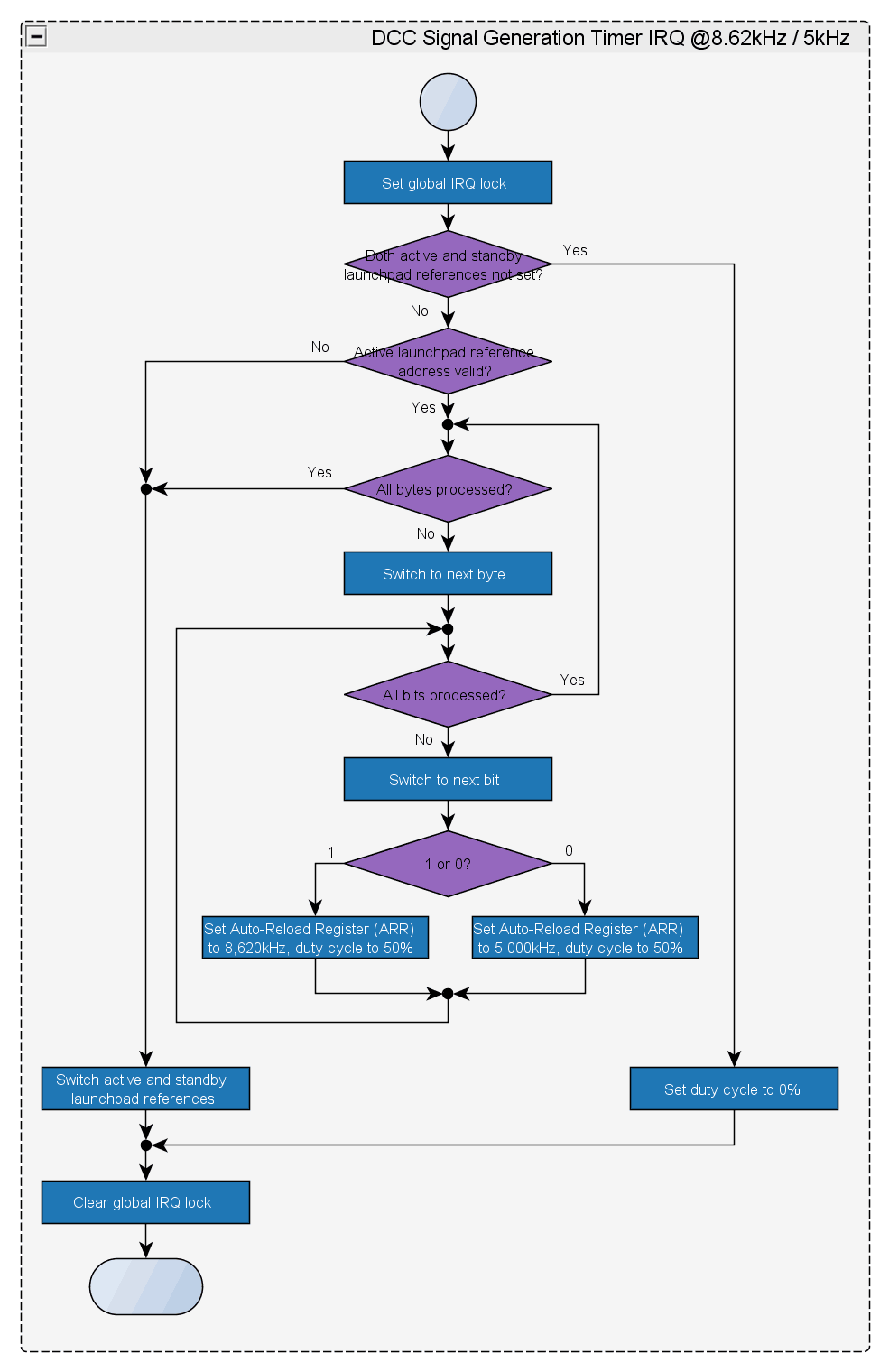 |
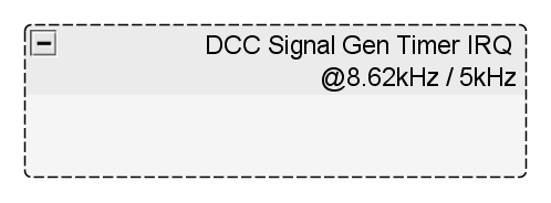
The DCC signal generator is based on a Pulse Width Modulation (PWM) timer interrupt whose frequency is controlled by the DCC signal itself and that has the highest interrupt priority. According to NMRA DCC-Specification S-9.1, a logical 1 is defined by a nominal signal length of 58us and a logical 0 is defined by a nominal signal length of 100us. Given a 50% duty cycle for switching between high and low signal level, this leads to timer frequencies of 8.62kHz for a logical 1 and 5.00kHz for a logical 0 (f=1/(0.000058s*2)and f=1/(0.0001s*2)).
If a timer interrupt is thrown (meaning one bit of the message was transmitted), all other interrupts get disabled. A state-machine then processes the DCC message section-, byte- and bit-wise and re-configures the Auto Reload Register depending on the current bit state to change the timer frequency accordingly. As soon as a message is completely transmitted, the address references of the active- and standby-launchpads will get switched for a seamless transition to the next DCC message.
Buffer
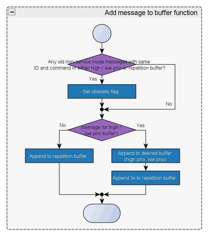 |
The function for appending a new DCC message to one of the three FIFO ringbuffers is called by the DCC Manager interrupt as well as for the generation of an emergency stop message. First of all the buffer is checked if it already contains messages of the same command type addressed to the same locomotive and if so, these messages are marked as obsolete. Depending on if the new command message shall be added to either the high- or low-prio buffer, the message also gets appended three times to the repetition buffer to ensure successful transmission even at poor rail-to-loco connection. If the new command message shall be directly added to the repetition buffer (e.g. in case the locomotive states are repeated from time to time), it only gets added to the repetition buffer.